Difference between revisions of "UPHCC Pinouts"
From UPHCC
| (6 intermediate revisions by the same user not shown) | |||
| Line 3: | Line 3: | ||
=== UPHCC-usb === | === UPHCC-usb === | ||
| + | UPHCC-usb module pinout: | ||
| + | * PNG format: [[Image:pinout_UPHCC_usb_rev0b.png]] | ||
| + | * PDF format: [[Media:pinout_UPHCC_usb_rev0b.pdf]] | ||
| + | |||
| + | ==== UPHCC-usb ICSP PIC Programming pinout ==== | ||
| + | |||
| + | ICSP pinout on the UPHCC-usb board for updating the bootloader in the PIC microcontroller. Note that the PGM pin does need to be controlled by the programmer. For low-voltage programmers already do the right thing, but some "standard" high-voltage programmers need to pull this pin to GND (at least during programming). | ||
| + | |||
| + | * PNG format: [[Image:UPHCC-usb_ICSPpinout.png|250px]] | ||
| + | * PDF format: [[Media:UPHCC_usb_ICSPpinout.pdf]] | ||
=== UPHCC-lcd === | === UPHCC-lcd === | ||
| Line 10: | Line 20: | ||
* PDF format [[Media:pinout_UPHCC_lcd_rev1.pdf]] | * PDF format [[Media:pinout_UPHCC_lcd_rev1.pdf]] | ||
| − | + | UPHCC-usb module to LCD pin mappings: | |
| + | * PNG format: [[Image:pinout_UPHCC_usb_rev0b_TO_lcd.png]] | ||
| + | * PDF format: [[Media:pinout_UPHCC_usb_rev0b_TO_lcd.pdf]] | ||
Latest revision as of 23:08, 28 April 2010
Contents
[hide]UPHCC Pinouts
UPHCC-usb
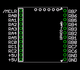
UPHCC-usb module pinout:
- PNG format:

- PDF format: Media:pinout_UPHCC_usb_rev0b.pdf
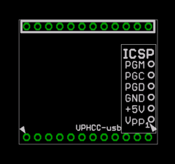
UPHCC-usb ICSP PIC Programming pinout
ICSP pinout on the UPHCC-usb board for updating the bootloader in the PIC microcontroller. Note that the PGM pin does need to be controlled by the programmer. For low-voltage programmers already do the right thing, but some "standard" high-voltage programmers need to pull this pin to GND (at least during programming).
- PNG format:

- PDF format: Media:UPHCC_usb_ICSPpinout.pdf
UPHCC-lcd
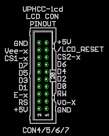
LCD Connector (CON4,CON5, CON6, CON7) pinout:
- PNG format:

- PDF format Media:pinout_UPHCC_lcd_rev1.pdf
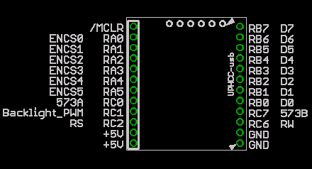
UPHCC-usb module to LCD pin mappings:
- PNG format:

- PDF format: Media:pinout_UPHCC_usb_rev0b_TO_lcd.pdf