Difference between revisions of "UPHCC-lcd Hardware Designs"
From UPHCC
m |
(PCB scans added) |
||
| Line 10: | Line 10: | ||
* archive of Gerber files: [[Media:UPHCC-lcd_rev1_gerbers.zip]] | * archive of Gerber files: [[Media:UPHCC-lcd_rev1_gerbers.zip]] | ||
* archive of Postscript files: [[Media:UPHCC-lcd_rev1_postscripts.zip]] | * archive of Postscript files: [[Media:UPHCC-lcd_rev1_postscripts.zip]] | ||
| + | |||
| + | == Printed Circuit Board == | ||
| + | * Top view: ''see box at right'' [[Image:UPHCC-lcd_pcb_top.jpg|thumbnail|right|200px|UPHCC-lcd PCB top]] | ||
| + | * Bottom view: ''see box at right'' [[Image:UPHCC-lcd_pcb_bottom.jpg|thumbnail|right|200px|UPHCC-lcd PCB bottom]] | ||
Revision as of 23:14, 3 January 2008
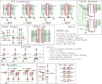
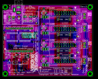
UPHCC-lcd Rev.1 schematics and layouts:
Schematics
- Eagle format: Media:UPHCC_lcd_rev1.sch.zip
- PNG format: see box at right
Layouts
- Eagle format: Media:UPHCC_lcd_rev1.brd.zip
- PNG format: see box at right
- archive of Gerber files: Media:UPHCC-lcd_rev1_gerbers.zip
- archive of Postscript files: Media:UPHCC-lcd_rev1_postscripts.zip
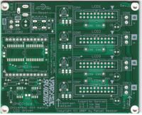
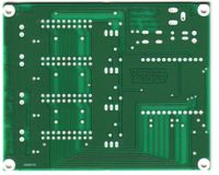
Printed Circuit Board
- Top view: see box at right
- Bottom view: see box at right


